Micro-inverter systems have become increasingly popular in residential solar installations due to their modularity, panel-level monitoring, improved safety, and better performance under shading conditions.
However, one important technical issue that is often overlooked during installation and system design is voltage rise.
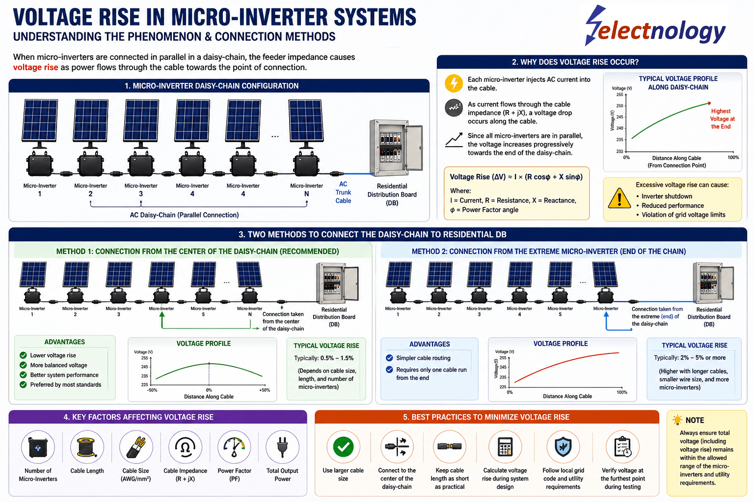
When multiple micro-inverters are connected in parallel through an AC trunk cable in a daisy-chain configuration, the voltage at different points of the cable does not remain equal. As power flows toward the residential Distribution Board (DB), cable impedance causes the voltage to rise progressively along the feeder.
If not properly managed, excessive voltage rise can:
- cause nuisance inverter tripping,
- reduce energy production,
- violate utility voltage limits,
- and create imbalance in system performance.
This article explains:
- Why voltage rise occurs in micro-inverter systems
- How daisy-chain topology affects voltage rise
- Two common methods of connecting the system to the residential DB
- Why center connection is often technically superior
- Best practices to minimize voltage rise
1. Typical Micro-Inverter Daisy-Chain Configuration
In a micro-inverter system:
- each PV module has its own micro-inverter,
- the DC power from the module is converted into AC locally,
- and all micro-inverter AC outputs are connected in parallel using a trunk cable.
A simplified arrangement looks like this:
PV + Micro-Inverter 1 ─┐
PV + Micro-Inverter 2 ─┤
PV + Micro-Inverter 3 ─┤── AC Trunk Cable ── Distribution Board
PV + Micro-Inverter 4 ─┤
PV + Micro-Inverter 5 ─┘As the currents from multiple inverters accumulate along the cable, the conductor experiences voltage rise due to its resistance and reactance.
2. Why Does Voltage Rise Occur?
Voltage rise is fundamentally caused by:
- cable resistance (R),
- cable reactance (X),
- and current flow (I).
The approximate voltage rise equation is:
ΔV=I(Rcosϕ+Xsinϕ)\Delta V = I(R\cos\phi + X\sin\phi)
Where:
- ΔV = Voltage rise
- I = Current flowing in the cable
- R = Cable resistance
- X = Cable reactance
- ϕ = Power factor angle
Each micro-inverter injects AC current into the trunk cable.
Near the farthest inverter:
- only one inverter current may be flowing.
Closer to the DB:
- the currents from many inverters combine together.
This means:
- the cable section near the DB carries the highest current,
- and therefore experiences the largest voltage rise.
As a result, the voltage progressively increases along the daisy-chain.
3. Why Excessive Voltage Rise Is a Problem
Modern micro-inverters continuously monitor grid voltage.
If the voltage exceeds allowable utility limits, the inverter may:
- reduce power output,
- disconnect from the grid,
- or repeatedly trip on overvoltage protection.
This can lead to:
- reduced energy yield,
- unstable operation,
- customer complaints,
- and non-compliance with grid standards.
4. Two Common Methods of Connecting the Daisy-Chain to the Residential DB
There are generally two ways to connect the AC trunk cable to the residential DB.
Method 1 — Connection from the Center of the Daisy-Chain (Recommended)
In this method:
- the AC connection to the DB is taken approximately from the middle of the micro-inverter string.
Example:
MI1 ─ MI2 ─ MI3 ─┬─ MI4 ─ MI5 ─ MI6
                 │
              To DB
Why This Method Is Better
The current flow becomes more balanced because:
- half the inverter current flows from one side,
- and the other half flows from the opposite side.
This reduces:
- maximum cable current,
- total voltage rise,
- and voltage imbalance.
Advantages
✔ Lower voltage rise
✔ Better voltage distribution
✔ Improved inverter stability
✔ Reduced nuisance tripping
✔ Better compliance with utility limits
Typical voltage rise in well-designed systems may remain around:
- 0.5%–1.5%.
Method 2 — Connection from the Extreme End of the Daisy-Chain
In this method:
- the DB connection is taken from one extreme end of the trunk cable.
Example:
MI1 ─ MI2 ─ MI3 ─ MI4 ─ MI5 ─ MI6 ─ To DBWhat Happens Here?
The cable section nearest the DB carries:
- the combined current of all micro-inverters.
Therefore:
- voltage rise accumulates continuously toward the end,
- resulting in higher voltage at distant inverters.
Disadvantages
❌ Higher voltage rise
❌ Greater chance of inverter tripping
❌ Reduced system efficiency
❌ Poorer voltage balance
Depending on:
- cable length,
- conductor size,
- number of micro-inverters,
- and system power,
voltage rise may exceed:
- 2%–5% or even more.
5. Key Factors Affecting Voltage Rise
Several parameters influence the severity of voltage rise:
| Factor | Effect |
|---|---|
| Cable Length | Longer cable = higher voltage rise |
| Cable Size | Smaller cable = higher resistance |
| Number of Micro-Inverters | More inverters = more current |
| Output Power | Higher power = higher current |
| Power Factor | Influences reactive component |
| Cable Material | Copper performs better than aluminum |
| Connection Topology | Center feed reduces rise |
6. Best Practices to Minimize Voltage Rise
To reduce voltage rise in micro-inverter systems:
- Use larger cable size
- Keep cable runs short
- Prefer center connection
- Divide large systems into multiple branches
- Verify voltage rise during design
- Follow utility and code limits
Many standards recommend keeping total voltage rise below:
- 2%–3%.
7. Final Thoughts
Micro-inverter systems provide excellent flexibility and module-level optimization, but their AC parallel architecture introduces unique voltage rise challenges.
The way the daisy-chain is connected to the residential DB has a major impact on:
- cable current,
- inverter operating voltage,
- and overall system reliability.
In many cases, simply connecting the system from the center of the daisy-chain instead of the extreme end can substantially reduce voltage rise and improve long-term performance.
For installers, designers, and engineers, understanding this phenomenon is essential for building efficient, compliant, and reliable solar PV systems.
Key Takeaway
📌 In micro-inverter systems, voltage rise is not just about cable size — connection topology matters significantly.
A center-fed daisy-chain often provides:
- better voltage balance,
- lower cable stress,
- and improved system stability compared to end-fed configurations.