Introduction
Proper conductor sizing is one of the most important aspects of photovoltaic (PV) system design. Undersized conductors can lead to overheating, insulation damage, nuisance trips, reduced system reliability, and even fire hazards.
NEC 690.8 is one of the prime sub-articles where in:
- NEC 690.8(A): Maximum Circuit Current
- NEC 690.8(B): Conductor Ampacity
This article focuses on two specialized but important provisions of NEC 690.8:
- NEC 690.8(C) — Systems with Multiple Direct-Current Voltages
- NEC 690.8(D) — Multiple PV String Circuits
Although these situations are less frequently encountered than standard PV source circuits, they address a critical engineering principle:
A conductor must be sized for the total current it may carry, not merely the current normally expected under operating conditions.
Why These Sub-Articles Exist
Most PV designers are familiar with sizing conductors based on a single circuit current. However, certain system configurations allow current contributions from multiple sources to flow through a single conductor.
Examples include:
- Common return conductors
- Parallel PV string circuits
- Fault current backfeed conditions
- Shared conductors between multiple circuits
In these situations, a conductor may carry significantly more current than a simple circuit calculation would suggest. NEC 690.8(C) and 690.8(D) ensure that these conductors are properly sized.
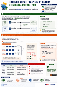
1) NEC 690.8(C) — Systems with Multiple Direct-Current Voltages
What Is the Clause Trying to Prevent?
This section applies when:
- A PV power source has multiple output voltages, and
- Those circuits share a common return conductor.
The NEC requires the ampacity of the common return conductor to be at least equal to the sum of the overcurrent device ratings protecting the individual circuits.
Simplified Concept
Imagine two DC circuits:
- Circuit A = 250 Vdc
- Circuit B = 500 Vdc
Both circuits share a common negative return conductor.
Diagram 1 – Multiple DC Voltages Sharing a Common Return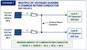
The shared return conductor may carry current from both circuits simultaneously. Therefore, it must be sized for the total possible return current.
Example Calculation
Assume:
- Circuit A protected by 20 A fuse
- Circuit B protected by 30 A fuse
Required common return conductor ampacity:
20 A + 30 A = 50 AWhy Is This Rare in Modern PV Systems?
This is one often asked by designers.
Most modern PV systems:
- Use separate positive and negative conductors
- Employ isolated circuits
- Utilize modern inverter architectures
- Avoid shared return conductors
As a result, NEC 690.8(C) is not commonly encountered in residential or commercial rooftop solar installations. However, NEC must cover all possible system architectures, including:
- Legacy systems
- Industrial DC systems
- Telecom systems
- Specialized power systems
- Bipolar PV systems
Historical Example: Bipolar PV Systems
Historically, bipolar PV arrays often used a common reference conductor.
Diagram 2 – Simplified Bipolar Arrangement
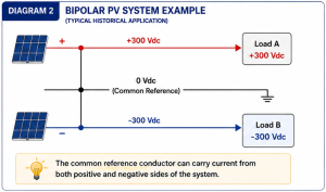
Such systems can create situations where one conductor carries current associated with multiple circuits.
2) NEC 690.8(D) — Multiple PV String Circuits
This section is much more common in practical PV design.
It addresses situations where:
- Multiple PV strings are connected in parallel.
- An overcurrent device protects those strings.
- Conductors may experience current contributions from other strings.
The Hidden Problem: Backfeed Current
Many designers initially assume that a string conductor only carries the current generated by its own string. That assumption is not always correct. During fault conditions, healthy strings can supply current into a faulted string.
This phenomenon is known as backfeed current.
Typical Configuration
Diagram 3 – Parallel PV Strings
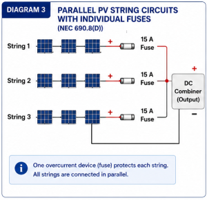
Under normal operation:
- Each string supplies current to the combiner.
Under fault conditions:
- Healthy strings can feed current into a faulted string.
- Conductors may carry more current than expected.
Why NEC Requires Additional Ampacity
NEC recognizes that a conductor protected by an overcurrent device may still experience additional current contributed by other strings.
Therefore conductor sizing must account for:
- The rating of the overcurrent device.
- Current contributions from other parallel strings.
Practical Example
Assume:
- Three PV strings
- Maximum current per string = 10 A
- String fuse = 15 A
Diagram 4 – Example System
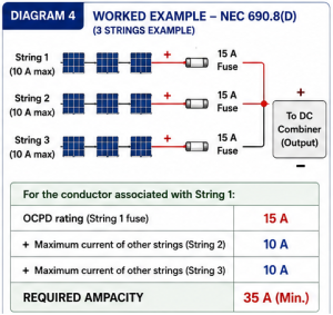
For the conductor associated with String 1:
Required ampacity:
= OCPD Rating + Current from Other Strings
= 15 A + (10 A + 10 A)
= 35 A
Why Doesn’t NEC Simply Use the Fuse Rating?
Many people ask:
“If the fuse is 15 A, why not size the conductor for 15 A?”
Because under fault conditions:
- String 2 contributes current.
- String 3 contributes current.
- The conductor may carry substantially more than 15 A.
The fuse rating alone does not represent the highest current the conductor could experience.
Visualizing Backfeed Current
Diagram 5 – Fault Current Flow
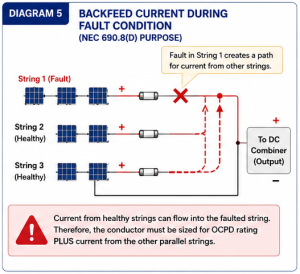
Current from String 2 and String 3 can flow toward the fault.
This additional current is precisely what NEC 690.8(D) addresses.
Comparing NEC 690.8(C) and NEC 690.8(D)
| Topic | NEC 690.8(C) | NEC 690.8(D) |
|---|---|---|
| Applies To | Multiple DC voltages sharing a return conductor | Multiple parallel PV strings |
| Main Concern | Combined return current | Backfeed current |
| Common in Modern PV? | Rare | Very Common |
| Conductor Sizing Basis | Sum of OCPD ratings | OCPD rating + current from other strings |
| Typical Application | Specialized DC systems | PV combiners and string circuits |
Common Design Mistakes
Mistake #1: Sizing a common return conductor for only one circuit.
Mistake #2: Ignoring current contributions from parallel strings.
Mistake #3: Assuming fuse rating alone determines conductor ampacity.
Mistake #4: Not considering fault current pathways.
Mistake #5: Failing to coordinate conductor ampacity with NEC 690.8(A) and 690.8(B).
Engineering Takeaway
NEC 690.8(C) and NEC 690.8(D) are based on a simple but extremely important engineering principle: Conductors must be sized for the highest current they can realistically carry. Sometimes that current comes from:
- Multiple circuits,
- Shared return conductors,
- Parallel string circuits,
- Or fault-induced backfeed currents.
Although NEC 690.8(C) is relatively uncommon in today’s solar installations, NEC 690.8(D) is encountered regularly in PV combiner and string-circuit design. Understanding these provisions helps designers select conductors that remain safe and code-compliant under both normal and abnormal operating conditions.
Key Takeaway
When multiple circuits contribute current to a conductor, size the conductor for the total possible current—not just the current of a single source.
This principle is the foundation of both NEC 690.8(C) and NEC 690.8(D) and is essential for safe, reliable, and code-compliant photovoltaic system design.