Voltage is one of the first parameters that must be established when designing a solar photovoltaic system.
It determines the voltage rating required for PV modules, conductors, cables, connectors, disconnects, overcurrent protection, inverters and other equipment. It also affects working-space requirements and the overall safety of the installation.
For PV systems, however, the voltage shown on a module datasheet is not necessarily the maximum voltage that the system can experience.
This is particularly important because PV module voltage increases as temperature decreases.
NEC Article 690.7 provides the requirements for determining the maximum DC voltage of a PV system.
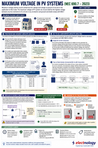
What Does “Maximum Voltage” Mean?
For a PV DC circuit, the maximum voltage is the highest voltage that can exist between any two circuit conductors, or between a conductor and ground, as applicable.
This value is then used when determining the voltage ratings of conductors, cables, equipment and other components.
In practical terms, the designer is asking:
What is the highest DC voltage this PV circuit could reasonably reach under the specified conditions?
The answer is particularly important under cold-weather conditions because PV module open-circuit voltage increases as temperature falls. NREL also highlights this effect and notes that an excessively high array voltage can damage inverter electronics.
Maximum PV System Voltage Limits
Under NEC 690.7, the maximum voltage limits include:
PV systems on or associated with buildings
PV DC circuits within or originating from arrays located on or attached to buildings, and PV DC circuits inside buildings, are limited to 1,000 V DC under the general rule.
One- and two-family dwellings
For one- and two-family dwellings, PV DC circuits are limited to 600 V DC.
Circuits above 1,000 V
The 2023 NEC introduced an important change concerning PV DC circuits exceeding 1,000 V. Such circuits must comply with the additional requirements of 690.31(G).
This does not mean that a conventional rooftop PV array can simply be designed above 1,000 V. The additional requirements and permitted locations must be carefully considered.
For engineers and designers, this is an important distinction:
The maximum voltage permitted by the Code depends not only on the equipment rating, but also on where and how the PV circuit is installed.
Why Is the Coldest Temperature Important?
A PV module’s nameplate open-circuit voltage, or Voc, is normally specified under standard test conditions.
But the actual Voc changes with temperature.
As the module becomes colder:
Voc increases
As the module becomes hotter:
Voc decreases
Therefore, using the module’s STC Voc directly to determine the maximum system voltage can underestimate the actual maximum voltage.
This is why NEC 690.7 requires the PV source-circuit voltage to be corrected for the lowest expected ambient temperature.
NREL provides a practical example showing that at an extreme minimum temperature of -25°C, the NEC correction factor is 1.20.
Calculating Maximum PV Source-Circuit Voltage
For a conventional PV string, the basic concept is:
Maximum PV Voltage = Number of Modules in Series × Corrected Module Voc
There are several permitted approaches under 690.7(A).
Method 1 — Use the Module Manufacturer’s Temperature Coefficient
If the module manufacturer provides the appropriate voltage temperature coefficient and calculation instructions, these values are used to determine the corrected Voc at the lowest expected temperature.
This is generally the preferred approach because it uses data specific to the actual module.
For example, suppose:
Module Voc at STC = 40 V
Number of modules in series = 10
Lowest expected temperature = -10°C
If the applicable temperature coefficient calculation produces a correction factor of 1.14, then:
Corrected module Voc = 40 × 1.14 = 45.6 V
Therefore:
Maximum string voltage = 45.6 × 10 = 456 V DC
This is the same basic calculation illustrated in our infographic.
The important point is that the calculation uses Voc, not Vmp.
Why Voc and Not Vmp?
This is a common point of confusion.
PV modules have several voltage specifications, including:
- Open-circuit voltage (Voc)
- Maximum-power voltage (Vmp)
Voc is the voltage when the module is not supplying current to a load.
Vmp is the voltage at the module’s maximum-power operating point.
For determining the maximum PV system voltage, Voc is the relevant parameter because the objective is to determine the highest possible circuit voltage.
Using Vmp would underestimate the maximum voltage.
Method 2 — NEC Table 690.7(A)
For crystalline and multicrystalline silicon modules, NEC 690.7(A) provides correction factors that can be used when applicable.
The principle is simple:
Corrected Voc = Rated Voc × Correction Factor
The correction factor increases as the expected minimum temperature becomes colder.
For example:
| Lowest Expected Ambient Temperature | Correction Factor |
|---|---|
| 24 to 20°C | 1.02 |
| 19 to 15°C | 1.04 |
| 14 to 10°C | 1.06 |
| 9 to 5°C | 1.08 |
| 4 to 0°C | 1.10 |
| -1 to -5°C | 1.12 |
| -6 to -10°C | 1.14 |
| -11 to -15°C | 1.16 |
| -16 to -20°C | 1.18 |
| -21 to -25°C | 1.20 |
| -26 to -30°C | 1.21 |
| -31 to -35°C | 1.23 |
| -36 to -40°C | 1.25 |
The important design principle is:
The colder the expected temperature, the greater the correction factor and therefore the higher the calculated maximum PV voltage.
The correction-factor approach is a convenient method for applicable crystalline and multicrystalline silicon modules. Where manufacturer temperature-coefficient information is available, the manufacturer’s specified calculation method should be followed.
Example: Determining the Maximum String Voltage
Consider a PV string with:
- Module Voc = 40 V
- 10 modules in series
- Lowest expected ambient temperature = -10°C
- Applicable correction factor = 1.14
First calculate the corrected module voltage:
40 × 1.14 = 45.6 V
Then calculate the maximum string voltage:
45.6 × 10 = 456 V DC
Therefore, the PV system designer should use approximately:
456 V DC
as the calculated maximum voltage for this string.
The next step is to verify that the applicable equipment, conductors and other components have voltage ratings suitable for this maximum voltage.
What Happens if We Add More Modules in Series?
Adding modules in series increases the string voltage.
For example:
10 modules × 40 V = 400 V at STC
But under the assumed cold condition:
10 × 40 × 1.14 = 456 V
If we increase the string to 13 modules:
13 × 40 × 1.14 = 592.8 V
And 14 modules would produce:
14 × 40 × 1.14 = 638.4 V
That could be a problem for a system subject to a 600 V maximum.
This illustrates why maximum series module count cannot be determined simply by dividing the inverter voltage rating by the module’s STC Voc.
The cold-temperature correction must be included.
Systems With Inverter Capacity of 100 kW or Greater
NEC 690.7(A) also provides an alternative calculation approach for PV systems with an inverter generating capacity of 100 kW or greater.
A documented and stamped PV system design using an industry-standard maximum-voltage calculation method may be provided by a licensed professional electrical engineer.
This provides a more engineering-based approach for larger systems rather than relying only on the standard correction-factor table.
For large commercial and utility-scale systems, detailed site-specific temperature and module characteristics can therefore become particularly important.
DC-to-DC Converter Circuits
Modern PV systems may contain DC-to-DC converters such as optimizers or other power-electronic devices.
NEC 690.7(B) addresses these circuits separately.
One DC-to-DC Converter
For a circuit connected to the output of a single DC-to-DC converter, the maximum voltage is determined according to the converter’s listing or labeling instructions.
If the manufacturer’s instructions do not provide a calculation method, the maximum rated output voltage of the converter is used.
Multiple Series-Connected Converters
If two or more DC-to-DC converters are connected in series, their maximum output voltages are considered together.
In simplified form:
Maximum Voltage = Converter 1 + Converter 2 + Converter 3 + …
This is particularly relevant when designing systems that use module-level power electronics.
The key lesson is:
Do not automatically apply the ordinary PV-module Voc calculation to the output of a DC-to-DC converter. Follow the converter’s listed instructions and ratings.
Bipolar PV Source Circuits
Bipolar PV systems are relatively uncommon in today’s installations, but NEC 690.7(C) addresses them.
In a bipolar arrangement, the maximum voltage for a monopole subarray circuit is determined by the voltage between the monopole conductors where one conductor is connected to the functionally grounded reference.
There is also an important safety requirement concerning isolation from ground to prevent excessive voltage during ground-fault or arc-fault conditions.
Although bipolar PV systems are not something most residential installers encounter regularly, the requirement demonstrates an important NEC principle:
Maximum voltage must be evaluated based on the actual circuit configuration, not simply by looking at individual module ratings.
Marking the Maximum DC Voltage
NEC 690.7(D) introduced a specific requirement for marking the highest maximum DC voltage calculated according to 690.7.
The installer must provide a permanent, readily visible label at one of the permitted locations:
- PV system DC disconnecting means
- PV system electronic power conversion equipment
- Distribution equipment associated with the PV system
This is useful to anyone who later works on the installation.
An electrician or technician should be able to identify the maximum DC voltage without having to reconstruct the original design calculations.
The 2023 NEC relocated the DC PV circuit marking requirement into 690.7(D), which is one of the notable organizational changes associated with this section.
Why Maximum Voltage Matters in Real PV Design
The maximum-voltage calculation is not just a paperwork exercise.
Once the maximum voltage has been established, it can affect the selection of:
- PV modules and string configuration
- Inverters
- DC disconnects
- Fuses and overcurrent protection
- Conductors and cables
- Connectors
- Combiner equipment
- DC surge protection
- Insulation ratings
- Other PV equipment
The calculated value should therefore be established before finalizing the system design.
A PV string that operates normally at 400 V may appear completely safe based on its normal operating voltage. But if its cold-weather open-circuit voltage can reach 500 V or more, the higher value is what matters when evaluating voltage ratings.
Maximum Voltage Is Not the Same as Operating Voltage
This distinction is worth emphasizing.
A PV system can have:
Vmp = 350 V
while its maximum calculated voltage might be:
Voc,max = 456 V
These are different quantities used for different design purposes.
Vmp helps us understand where the array normally operates and is important for inverter MPPT design.
Voc,max is important for establishing the maximum DC voltage and ensuring that equipment and wiring are appropriately rated.
Confusing these two values can lead to an incorrect string design.
A Practical Design Sequence
For a conventional PV string, the design process can be summarized as:
1. Obtain the module Voc.
2. Obtain the manufacturer’s Voc temperature coefficient and applicable calculation instructions.
3. Determine the lowest expected temperature at the installation location.
4. Calculate the temperature-corrected Voc.
5. Multiply by the number of modules connected in series.
6. Compare the resulting maximum voltage with the applicable NEC voltage limit.
7. Verify the voltage ratings of the inverter, disconnects, conductors, connectors and other equipment.
8. Provide the required maximum-voltage marking.
For large systems, also determine whether the alternative professional-engineer calculation method under 690.7(A) is applicable.
A Common Design Mistake
One of the most common mistakes is to calculate:
Maximum voltage = Module Voc × Number of modules
and stop there.
For example:
40 V × 12 = 480 V
This may look acceptable for a 600 V system.
But if the lowest expected temperature requires a 1.14 correction factor:
40 × 12 × 1.14 = 547.2 V
The result is substantially higher.
This is why cold-weather voltage correction is a critical part of PV string sizing.
Final Takeaway
NEC 690.7 is essentially about answering one fundamental question:
What is the highest DC voltage that the PV system or a particular PV circuit can be expected to experience?
For conventional PV strings, the most important factors are:
Module Voc + Number of Modules in Series + Lowest Expected Temperature
The resulting maximum voltage is then used to verify the system’s voltage limits and equipment ratings.
For systems using DC-to-DC converters, bipolar configurations or large inverter capacities, additional requirements apply.
The most important practical lesson is simple:
Never size a PV string using the module’s STC Voc alone. Always consider the lowest expected temperature and determine the maximum system voltage before finalizing the string configuration.
Accurate maximum-voltage calculations are one of the foundations of a safe, code-compliant and reliable PV system.