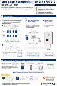
 Designing a safe photovoltaic system is not simply a matter of selecting a conductor based on the normal operating current of a PV array. Solar PV circuits can operate continuously for long periods, and their current can vary with irradiance, temperature, system configuration, and environmental conditions. The National Electrical Code (NEC) Article 690.8 therefore establishes a structured method for determining both the maximum circuit current and the minimum conductor ampacity.
Two parts are particularly important:
- NEC 690.8(A) — Calculation of Maximum Circuit Current
- NEC 690.8(B) — Conductor Ampacity
The relationship is straightforward:
690.8(A) determines how much current is flowing in the the circuit which essentially establishes the basis for Conductor Ampacity.
690.8(B) determines how much ampacity the conductor must have depending upon how much Current is flowing n the Conductor.
These calculations are fundamental to PV conductor sizing, overcurrent protection, and equipment selection.
1. Why NEC 690.8 Matters
A PV module may have a relatively modest short-circuit current, but when multiple PV strings are connected in parallel, their currents add together. For example, if each PV string has a short-circuit current of 12 A and four strings are connected in parallel:
12 A × 4 = 48 A
But NEC 690.8(A) does not simply use 48 A as the design maximum current. The applicable calculation method must be applied. That calculated maximum current then becomes the basis for conductor ampacity and other circuit-sizing decisions. This two-step approach is important because maximum circuit current and conductor ampacity are not the same thing.
2. NEC 690.8(A) — Calculation of Maximum Circuit Current
For PV system circuits, NEC 690.8(A) establishes different methods depending on the type of circuit.
For the 2023 NEC, the major categories include:
- PV source circuit current
- PV DC-to-DC converter circuit current
- Inverter output circuit current
- Circuits connected to the input of electronic power converters
2.1 PV Source Circuit Current
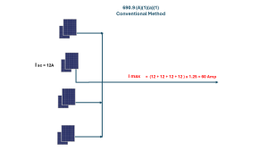
For the conventional calculation method, the maximum current is based on the short-circuit current ratings of PV modules connected in parallel, multiplied by 125%. In simplified form:
Maximum Circuit Current = Sum of Parallel PV Module Isc × 1.25
The important point is that current is additive in parallel. For example, assume a PV arrangement has four parallel strings and each string has a short-circuit current of 12 A. The maximum circuit current is:
(12 + 12 + 12 + 12) × 1.25 = 48 × 1.25 = 60 A
Therefore, 60 A becomes the maximum circuit current used in subsequent circuit-sizing calculations. The 125% factor in 690.8(A) should not be confused with the additional 125% requirement that can arise under 690.8(B)(1). They serve different purposes.
3. Engineered Method for Large PV Systems
NEC 690.8(A) also permits an alternative engineered method for PV systems with an inverter generating capacity of 100 kW or greater. Under this approach, a documented and stamped PV system design prepared using an industry-standard maximum-current calculation by a licensed professional electrical engineer is permitted.
The calculation is based on the highest three-hour current average obtained from simulated local irradiance while accounting for factors such as:
- Elevation
- Array orientation
- Local irradiance conditions
There is also an important limitation: the calculated current cannot be less than 70% of the value obtained using the conventional 125% short-circuit-current method. This method recognizes that large PV plants can have site-specific irradiance characteristics that may not be represented adequately by simply applying the standard 125% factor. It is particularly relevant to larger commercial and utility-scale PV projects.
4. PV DC-to-DC Converter Circuit Current
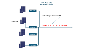
Modern PV systems may include DC-to-DC converters such as module-level power optimizers or other DC conversion equipment. For circuits involving multiple DC-to-DC converters connected in parallel, NEC 690.8(A) uses the sum of their continuous output current ratings. For example, if three parallel DC-to-DC converters have continuous output ratings of:
- Converter 1 = 16 A
- Converter 2 = 16 A
- Converter 3 = 16 A
- Converter 4 = 16 A
Then: Maximum Circuit Current = 15 + 15 + 15 = 45 A
The manufacturer’s listing and installation instructions must also be considered when applying the requirements to a particular product.
5. Inverter Output Circuit Current
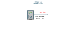
For the inverter output circuit, the maximum current is based on the inverter’s continuous output current rating.
For example, if a grid-connected inverter has a continuous AC output current rating of 70 A:
Maximum Circuit Current = 70 A
This value is then used in the subsequent conductor-sizing calculation under 690.8(B).
This is an important distinction from the PV DC side. The designer does not calculate the inverter output current by multiplying the PV module Isc by 125%. The inverter’s applicable continuous output rating is used.
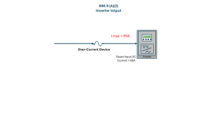
6. Circuits Connected to Electronic Power Converter Inputs
NEC 690.8(A) also provides a provision for certain circuits connected to the input of an electronic power converter. Where the required conditions are satisfied, including appropriate overcurrent protection, the maximum current may be based on the rated input current of the electronic power converter. This converter can be an Inverter. This can be useful in systems where the electronic power converter itself establishes a controlled input-current limit. The designer should verify the converter listing, manufacturer’s instructions, conductor ampacity and overcurrent protection requirements rather than automatically applying the conventional PV source-circuit calculation. In the example shown, rated Input Current for the Inverter is 65A, hence maximum current to be established fot the Conductor shall also be taken as 65A.
7. NEC 690.8(B) — Conductor Ampacity
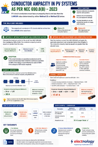
Once the maximum circuit current has been determined under NEC 690.8(A), the next question is: How large must the conductor be? NEC 690.8(B) requires PV circuit conductors to have an ampacity not less than the larger of the values determined using 690.8(B)(1), without adjustment and correction factors, and 690.8(B)(2), with adjustment and correction factors.
This is important because a conductor that appears adequate from its normal ampacity table rating may not remain adequate when it is installed in a hot environment or together with several other current-carrying conductors. The designer therefore needs to perform both checks and use the result that imposes the greater requirement.
8. 690.8(B)(1) — Without Adjustment and Correction Factors
Under the first method, take the maximum current calculated under 690.8(A) and multiply it by 125%:
Required Conductor Ampacity = Maximum Circuit Current × 1.25
For example, if the maximum circuit current is 60 A:
Required Ampacity = 60 × 1.25 = 75 A
Therefore, under 690.8(B)(1), the selected conductor must have an applicable ampacity of at least 75 A, before considering adjustment and correction factors.
This is the familiar second 125% calculation in a conventional PV source-circuit calculation. The first 125% and second 125% should not be confused. The first is used in determining the PV maximum circuit current under 690.8(A), while the second is used for conductor ampacity under 690.8(B)(1):
Module Isc → 125% under 690.8(A) → Maximum Circuit Current → 125% under 690.8(B)(1) → Required Conductor Ampacity
For example, if one PV string has an Isc of 12 A, then 12 × 1.25 = 15 A maximum circuit current. The conductor ampacity under 690.8(B)(1) would then be 15 × 1.25 = 18.75 A.
9. The 100% Continuous-Operation Exception
There is an exception to 690.8(B)(1) for certain assemblies, together with their overcurrent devices where applicable, that are listed for continuous operation at 100% of their rating. Where all requirements of the exception are satisfied, the equipment may be used at 100% of its rating rather than applying the 125% multiplier under 690.8(B)(1).
This is not a general permission to omit the 125% factor simply because a PV circuit operates continuously. The equipment must be appropriately listed for 100% continuous operation, and the complete installation must satisfy the applicable NEC requirements.
10. 690.8(B)(2) — With Adjustment and Correction Factors
The second method is particularly important in PV installations because conductors are often exposed to elevated temperatures and may be installed together in raceways, cable assemblies, or other configurations containing multiple current-carrying conductors.
Under 690.8(B)(2), the maximum current calculated under 690.8(A) must be accommodated after the applicable conductor adjustment and correction factors are applied. In practical terms, the designer determines the conductor’s base ampacity, applies the applicable temperature correction factor and adjustment factor, and verifies that the resulting allowable ampacity is at least the maximum current from 690.8(A).
The basic relationship is:
Adjusted/Corrected Ampacity = Base Ampacity × Temperature Correction Factor × Adjustment Factor
Therefore, when determining the minimum required base ampacity:
Required Base Ampacity ≥ Maximum Circuit Current ÷ (Temperature Correction Factor × Adjustment Factor)
This distinction is important. The adjustment and correction factors are applied to the conductor ampacity, not simply multiplied by the maximum circuit current to produce a smaller required ampacity.
11. What Are Adjustment and Correction Factors?
The terms correction factor and adjustment factor refer to different installation conditions. The two most important factors for typical PV conductor calculations are temperature correction and number of current-carrying conductors.
Temperature Correction Factor
The temperature correction factor accounts for an ambient temperature different from the reference temperature used by the NEC ampacity tables. For the commonly used ampacity tables based on 30°C (86°F), NEC Table 310.15(B)(1) provides correction factors based on ambient temperature and conductor temperature rating. Taking an example, for a 90°C-rated conductor, representative correction factors include:
| Ambient Temperature | 90°C Correction Factor |
|---|---|
| 26–30°C | 1.00 |
| 31–35°C | 0.96 |
| 36–40°C | 0.91 |
| 41–45°C | 0.87 |
| 46–50°C | 0.82 |
| 51–55°C | 0.76 |
| 56–60°C | 0.71 |
| 61–70°C | 0.58 |
| 71–75°C | 0.50 |
| 76–80°C | 0.41 |
For example, at 40°C ambient, the correction factor for a 90°C-rated conductor is 0.91. If the conductor’s base ampacity is 40 A, its corrected ampacity before applying any other adjustment factor would be:
40 × 0.91 = 36.4 A
Thus, its corrected ampacity becomes 36.4 A before considering additional adjustment factors.
Important Point About 60°C, 75°C and 90°C Ratings
The correction factor must correspond to the temperature rating being used for the conductor ampacity calculation. A 90°C-rated conductor can generally use the 90°C correction-factor column when permitted by the applicable NEC requirements, but the final allowable ampacity can still be limited by the temperature rating of the equipment terminations under NEC 110.14(C).
Therefore:
90°C conductor insulation rating ≠ automatically 90°C allowable termination temperature
This distinction is particularly important when selecting conductors for PV equipment.
12. Adjustment Factor — Number of Current-Carrying Conductors
The second major factor is the adjustment factor for multiple current-carrying conductors. When several current-carrying conductors are installed together, heat generated by one conductor affects the others. The NEC therefore requires ampacity adjustment when the applicable number of current-carrying conductors exceeds three.
NEC Table 310.15(C)(1) provides adjustment factors such as:
| Number of Current-Carrying Conductors | Adjustment Factor |
|---|---|
| 1–3 | 100% |
| 4–6 | 80% |
| 7–9 | 70% |
| 10–20 | 50% |
| 21–30 | 45% |
| 31–40 | 40% |
| 41 and above | 35% |
For example, if a raceway contains 7 applicable current-carrying conductors, the adjustment factor is 70% or 0.70. If the base conductor ampacity is 40 A, the adjusted ampacity would be:
40 × 0.70 = 28 A
The adjustment factor is specifically concerned with the thermal effect of multiple current-carrying conductors. It should not be confused with the separate physical conduit-fill calculation.
12.1 What Counts as a Current-Carrying Conductor?
This is an important practical question. The number of conductors used to select the adjustment factor is determined according to the NEC rules for current-carrying conductors, including the applicable provisions of 310.15(E) and 310.15(F). Equipment grounding conductors, for example, generally do not count as current-carrying conductors.
The designer should therefore not simply count every wire physically present in a raceway. The actual circuit configuration must be evaluated according to the applicable NEC requirements.
13. Rooftop Temperature — Particularly Important for PV Systems
PV installations require additional attention to conductor temperature because conductors are frequently installed on rooftops, above rooftops, in direct sunlight, near hot roof surfaces, or beneath PV modules. NEC provisions address raceways and cables exposed to direct sunlight on or above rooftops. Where the applicable rooftop condition applies i.e. if the conductor is at 7/8 inches or less insalled above the roof top then specified temperature adder must be added to the outdoor ambient temperature before determining the applicable temperature correction factor.
For example, suppose the applicable outdoor design temperature is 40°C and the installation requires a 33°C rooftop temperature adder. The effective temperature for the applicable calculation would become:
40°C + 33°C = 73°C
The appropriate temperature correction factor is then selected based on this effective temperature and the conductor’s temperature rating. This can have a major impact on conductor ampacity and is one reason why simply taking a conductor’s Table 310.16 ampacity and assuming that it applies unchanged to a rooftop PV installation can produce an incorrect result.
14. Applying Both Temperature and Conductor-Count Factors
When both conditions apply, the factors are applied to the conductor’s base ampacity. For example, suppose:
- Base conductor ampacity = 40 A
- Temperature correction factor = 0.91
- Current-carrying conductor adjustment factor = 0.80
Then:
Adjusted Ampacity = 40 × 0.91 × 0.80 = 29.12 A
If the maximum circuit current from 690.8(A) is 24 A, then:
29.12 A ≥ 24 A
Therefore, the conductor satisfies the 690.8(B)(2) ampacity check, assuming all other applicable requirements are satisfied. The factors are multiplicative, not additive. In other words, you do not calculate 0.91 + 0.80; you calculate 0.91 × 0.80.
15. Worked Example — Correct Application of 690.8(B)(2)
Consider a PV circuit with a maximum circuit current from 690.8(A) of 24 A. Suppose the installation conditions produce a temperature correction factor of 0.91 and an adjustment factor of 0.80.
The combined factor is:
0.91 × 0.80 = 0.728
The selected conductor must retain at least 24 A after these factors are applied. Therefore:
Required Base Ampacity = 24 ÷ 0.728 = 32.97 A
Thus, the selected conductor needs a base ampacity of at least approximately 33 A before application of the two factors. Now consider a candidate conductor with a base ampacity of 40 A:
40 × 0.91 × 0.80 = 29.12 A
Since 29.12 A ≥ 24 A, the conductor passes the 690.8(B)(2) check. This is the correct way to understand the adjustment/correction-factor calculation.
16. Comparing 690.8(B)(1) and 690.8(B)(2)
Now consider the same circuit with a maximum circuit current of 24 A.
Under Method (1): 24 × 1.25 = 30 A
Therefore, Method (1) requires a conductor ampacity of at least 30 A.
Under Method (2), with a temperature correction factor of 0.91 and adjustment factor of 0.80:
Combined factor = 0.91 × 0.80 = 0.728
Required Base Ampacity = 24 ÷ 0.728 = 32.97 A
The comparison is therefore:
| 690.8(B) Method | Required Base Ampacity |
|---|---|
| (B)(1) Without factors | 30 A |
| (B)(2) With factors | 32.97 A |
| Governing requirement | 32.97 A |
In this example, 690.8(B)(2) governs because the conductor needs a base ampacity of approximately 33 A to retain at least 24 A after the applicable adjustment and correction factors are applied.
17. A Practical PV Conductor-Sizing Sequence
For a typical PV circuit, the following sequence provides a useful engineering workflow:
- Identify the circuit. Determine whether it is a PV source circuit, DC-to-DC converter circuit, inverter output circuit, or circuit connected to an electronic power converter input.
- Calculate maximum circuit current. Apply the appropriate method under 690.8(A).
- Perform the 690.8(B)(1) calculation. Calculate maximum current × 125% to establish the conductor ampacity requirement without adjustment and correction factors.
- Determine installation conditions. Check ambient temperature, rooftop exposure, direct sunlight, number of current-carrying conductors, raceway/cable arrangement, conductor insulation temperature rating, and other applicable conditions.
- Determine the temperature correction factor. Use the applicable NEC temperature correction table based on effective ambient temperature and conductor temperature rating. For rooftop installations, determine whether the applicable rooftop temperature provision applies.
- Determine the conductor adjustment factor. Count the applicable current-carrying conductors and use NEC Table 310.15(C)(1).
-
Perform the 690.8(B)(2) calculation. Verify that the selected conductor’s adjusted/corrected ampacity is at least the maximum circuit current from 690.8(A):
Adjusted Ampacity = Base Ampacity × Temperature Factor × Adjustment Factor
- Compare the two methods. The conductor must satisfy the larger governing requirement from 690.8(B)(1) and 690.8(B)(2).
- Check termination limitations. Verify that the selected conductor and its ampacity are compatible with equipment termination requirements, including applicable provisions of NEC 110.14(C).
- Complete the other NEC checks. Verify overcurrent protection, installation method, conductor ratings, equipment listing, voltage drop where applicable, and manufacturer instructions.
18. Worked Example — Complete PV Source Circuit
Consider a PV system with 4 parallel PV strings, where each string has an Isc of 12 A.
Step 1 — Maximum Circuit Current
Using 690.8(A):
Maximum Circuit Current = 4 × 12 × 1.25 = 60 A
Therefore, the maximum circuit current is 60 A.
Step 2 — 690.8(B)(1)
Required Ampacity = 60 × 1.25 = 75 A
Therefore, Method (1) requires a conductor with an applicable ampacity of at least 75 A before adjustment and correction factors.
Step 3 — 690.8(B)(2)
Suppose the actual installation produces:
- Temperature correction factor = 0.91
- Adjustment factor = 0.80
Combined factor:
0.91 × 0.80 = 0.728
Required base ampacity:
60 ÷ 0.728 = 82.42 A
Therefore:
| Method | Requirement |
|---|---|
| 690.8(B)(1) | 75 A |
| 690.8(B)(2) | 82.42 A |
| Governing requirement | 82.42 A |
The 690.8(B)(2) condition is more restrictive. The designer therefore needs a conductor whose applicable base ampacity is at least approximately 82.4 A, subject to the applicable NEC ampacity table, conductor type, material, installation method, temperature rating, termination limitations, and other requirements.
19. Why PV Systems Need Special Attention
PV circuits differ from many conventional electrical circuits because their current originates from an energy source that varies with solar irradiance. A module’s nameplate Isc is therefore not automatically the final current used for conductor sizing. NEC 690.8 establishes a calculation process that accounts for the applicable PV circuit configuration and then requires the conductor to have adequate ampacity under the actual installation conditions.
This becomes especially important when multiple strings are connected in parallel, conductors are installed in common raceways, ambient temperatures are high, conductors are installed near rooftops, large commercial PV arrays are designed, or DC-to-DC converters are used. Designers should also consider applicable module labeling, listing information, and manufacturer installation instructions for specialized PV modules and equipment.
20. Maximum Current vs. Ampacity — The Key Concept
Perhaps the easiest way to remember NEC 690.8 is:
690.8(A) tells us how much current the circuit must be designed for. 690.8(B) tells us how much ampacity the conductor must safely provide under the applicable conditions.
These are related, but they are not the same number. The overall relationship can be summarized as:
PV Module / Converter / Inverter → 690.8(A) → Maximum Circuit Current → 690.8(B) → Required Conductor Ampacity
For 690.8(B)(2), the conductor must continue to provide adequate ampacity after the applicable adjustment and correction factors have been applied.
21. Common Design Mistakes
Mistake 1 — Using Operating Current Instead of Isc
For the applicable PV source-circuit calculation, the designer should use the appropriate short-circuit-current method specified by 690.8(A), rather than simply using the normal operating current.
Mistake 2 — Forgetting That Parallel Currents Add
When PV strings are connected in parallel, their currents add together before the applicable 690.8(A) calculation is performed.
Mistake 3 — Confusing the Two 125% Factors
The 125% factor in 690.8(A) and the 125% factor in 690.8(B)(1) serve different purposes. The first establishes maximum PV circuit current; the second establishes the conductor ampacity requirement under Method (1).
Mistake 4 — Treating Adjustment Factors as Temperature Factors
The number of current-carrying conductors and ambient temperature are separate conditions and use different NEC provisions and tables.
Mistake 5 — Multiplying Maximum Current by Derating Factors
This is perhaps the most important mistake to avoid. For example, this is not the correct interpretation:
24 × 0.80 × 0.91 = 17.47 A
and then calling 17.47 A the required conductor ampacity. Instead, the conductor’s base ampacity is reduced by the factors, and the resulting ampacity must still be at least 24 A:
Base Ampacity × 0.80 × 0.91 ≥ 24 A
Therefore:
Base Ampacity ≥ 24 ÷ (0.80 × 0.91) = 32.97 A
This is a critical distinction when applying 690.8(B)(2).
Mistake 6 — Ignoring Rooftop Temperature
A rooftop PV installation can have considerably higher conductor temperatures than the reported outdoor ambient temperature. Where the applicable NEC rooftop provision applies, the required temperature adder must be considered before selecting the temperature correction factor.
Mistake 7 — Counting Every Conductor as Current-Carrying
The NEC has specific rules for determining which conductors count as current-carrying conductors. Do not simply count every wire physically present in the raceway.
Mistake 8 — Assuming a 90°C Conductor Can Always Operate at 90°C
The conductor insulation rating and the equipment termination temperature rating are separate considerations. The final allowable ampacity may be limited by the equipment termination requirements.
Mistake 9 — Stopping After Conductor Sizing
The final PV design must also satisfy applicable requirements for overcurrent protection, terminations, raceway and cable installation, conductor temperature rating, voltage drop where applicable, equipment listing, manufacturer instructions, and other relevant NEC requirements.
22. How 690.8(A) and 690.8(B) Fit Together
The complete design logic can be represented as:
PV Module / DC-to-DC Converter / Inverter
↓
Determine Maximum Circuit Current — 690.8(A)
↓
Method 1: 690.8(B)(1) — Maximum Current × 125%
Method 2: 690.8(B)(2) — Check conductor ampacity after applicable adjustment and correction factors
↓
Compare the two requirements
↓
Use the larger governing requirement
↓
Check conductor temperature rating and equipment terminations
↓
Verify overcurrent protection and other applicable NEC requirements
This sequence provides and established a practical framework for applying NEC 690.8 during PV system design.
Conclusion
NEC 690.8 is one of the most important sections for PV electrical design because it connects the electrical characteristics of the PV system to the required conductor ampacity. This Article determines the maximum circuit current based on the particular PV circuit configuration. NEC 690.8(B)(1) checks the conductor requirement using the 125% method without adjustment and correction factors, on the other hand, NEC 690.8(B)(2) checks whether the conductor can still carry the maximum circuit current after the applicable installation condition factors are applied.